Published configuration highlights
- Model and functionWKS-23 / Digital Temperature Transmitter with LCD
- Key point 1-50 to 400°C
- Key point 2Local display
- Key point 3RS-485 option
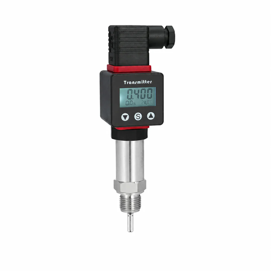
A locally indicating temperature transmitter for heating, cooling, liquid, oil, and gas service from -50 to 400°C. It uses a 12-36 VDC supply, supports G1/2 or M20×1.5 process threads, and is available with 4-20 mA, voltage, switch, or RS-485 output.
Confirm the measuring range, medium, wetted materials, process connection, output, and power supply before ordering.
Use the published values below as a starting point, then confirm the complete measuring point before ordering. Final range, materials, connection, output, supply, and environmental limits depend on the selected configuration.
Install the sensing probe at the required immersion depth and connect the configured transmitter output to the PLC, controller, or indicator. Confirm the sensing element, temperature range, probe diameter, insertion length, and process connection.
Check sensor wiring, transmitter range, engineering units, loop direction, and the installed reading against a suitable reference at the operating condition.
Select the sensing element and calibrated range for the required accuracy, operating temperature, and control-system input.
Confirm probe diameter, insertion length, connection, thermowell, pressure exposure, vibration, and access for removal.
Place the sensing tip in representative flow and account for immersion error, thermal lag, stem conduction, and nearby heat sources.
Suitability is configuration-dependent. Review media compatibility, operating limits, installation conditions, required approvals, and the receiving control system before final selection.