
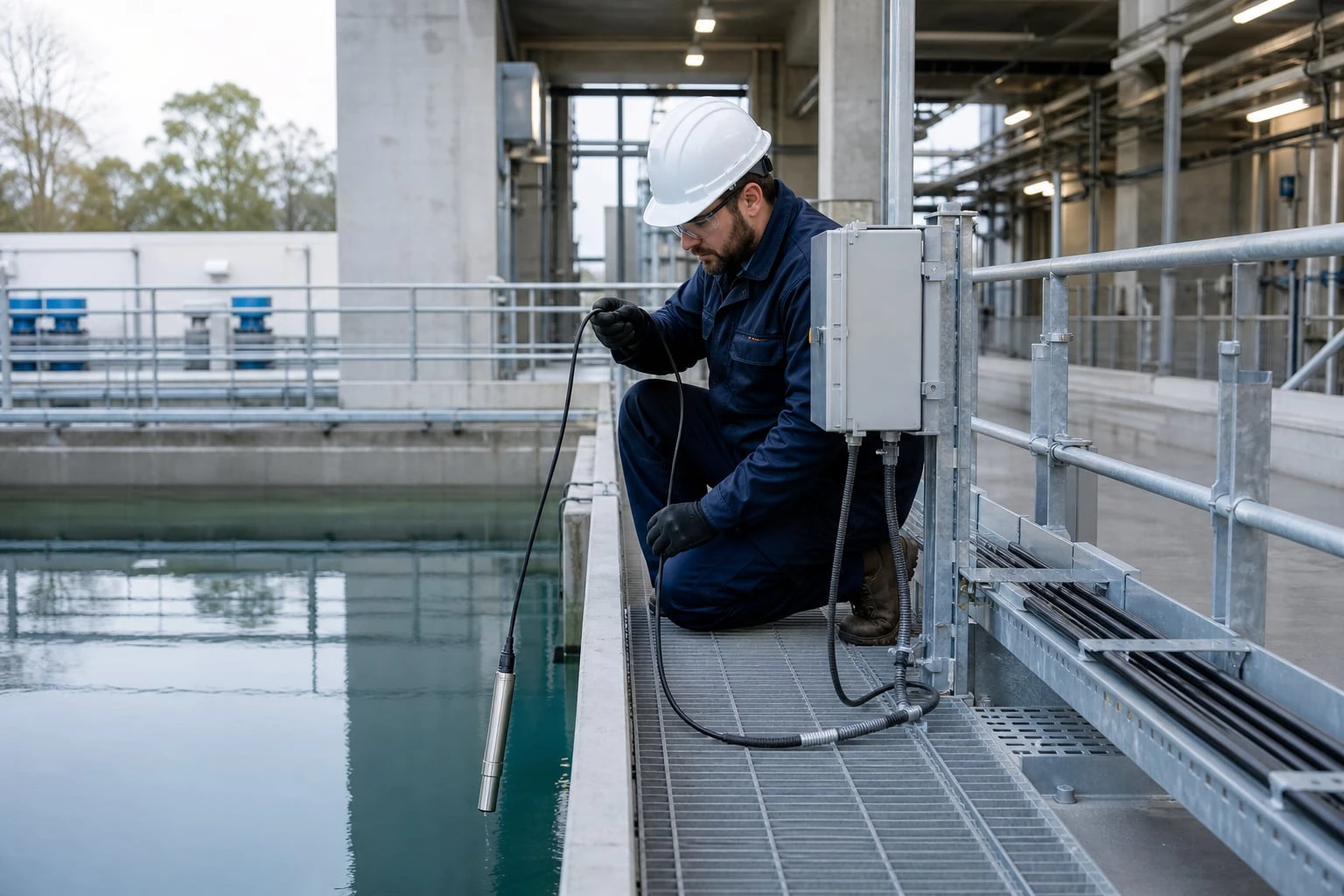
A hydrostatic level transmitter measures liquid depth from the pressure created by the liquid column above its sensing diaphragm. Installation accuracy therefore depends on more than the transmitter’s stated accuracy: liquid density, atmospheric venting, sensor elevation, cable condition, electrical interference, and commissioning references all affect the reported level.
For a vented submersible transmitter in an open tank, install the sensing diaphragm at a known elevation, keep the cable vent path dry and open to atmosphere, protect the cable from load and damage, and verify the zero and span against known liquid levels. A transmitter can be correctly calibrated at the factory yet still indicate the wrong level if its vent is blocked, its density basis is wrong, or its installed elevation has not been accounted for.
Start with the hydrostatic pressure relationship
Hydrostatic pressure is the pressure caused by the weight of liquid above a point. For a static liquid:
P = ρ g h
Where:
P= hydrostatic pressure at the sensing diaphragmρ= liquid densityg= gravitational acceleration, approximately 9.80665 m/s²h= vertical liquid height above the diaphragm
For an open, vented vessel, the transmitter measures gauge pressure: pressure relative to local atmospheric pressure. Atmospheric pressure is applied to one side of the sensing element through the vented cable, while the process pressure acts on the diaphragm.
For a closed or pressurized vessel, the pressure at the bottom includes both the liquid head and vessel pressure. A single pressure transmitter cannot separate those two terms. Differential-pressure measurement or another suitable method is generally needed when vessel pressure varies.
Illustrative pressure-to-level calculation
Assume a vented tank contains water with a density of 998 kg/m³ and the liquid depth above the transmitter is 12 ft.
First, convert depth:
12 ft × 0.3048 = 3.658 m
Then calculate pressure:
P = 998 kg/m^3 × 9.80665 m/s^2 × 3.658 m
P ≈ 35,800 Pa
That is approximately:
- 35.8 kPa
- 5.19 psi
- 12 ft of water column under the stated density assumption
The result is illustrative. Water density changes with temperature and composition, and non-water liquids may produce substantially different pressure at the same depth.
A useful approximation for water near ordinary ambient conditions is:
1 ft of water ≈ 0.433 psi
Use this only as a preliminary check. Final range selection and scaling should use the expected liquid density and the actual measurement datum.
Convert pressure range to level using actual density
A level transmitter does not directly measure distance. It measures pressure and the control system converts that pressure to level using an assumed density. If actual density differs from the configured density, the indicated level will be proportionally wrong.
Rearranging the hydrostatic equation:
h = (P) / (ρ g)
For a fixed measured pressure, a lower-density liquid produces a greater actual height. A higher-density liquid produces a lower actual height.
Density error becomes level error
Suppose a system scales pressure as if the liquid density were 1,000 kg/m³, but the actual density is 950 kg/m³. At a true liquid level of 10 ft, the pressure is lower than the system expects for 10 ft. The indicated level will be approximately:
10 ft × (950) / (1000) = 9.5 ft
Under these assumptions, the system reads about 0.5 ft low.
This is not transmitter error. It is a conversion error caused by the density assumption.
Before selecting the pressure range, define:
- Minimum and maximum liquid density across temperature, concentration, and batch conditions.
- Normal operating level and maximum credible liquid height.
- Required headroom above normal maximum level, if overfill conditions must be detected.
- Minimum useful level, especially if the diaphragm sits above the vessel floor.
- Whether density is stable enough for pressure-derived level to meet the control or inventory requirement.
For variable-density liquids, possible approaches include:
- Scale to a nominal density and document the resulting uncertainty.
- Apply density compensation if a reliable density or temperature relationship is available.
- Use pressure level for alarms or control while using another method for high-accuracy inventory.
- Select a different level-measurement principle when density variation dominates the allowable error.
Do not select the pressure range solely from vessel height. A range sized for 20 ft of water may be inadequate for 20 ft of a denser brine, slurry, or process solution.
Separate transmitter accuracy from installed uncertainty
A transmitter’s published accuracy describes performance under the manufacturer’s stated reference conditions. Total installed level uncertainty also includes:
- Density variation or density-assumption error
- Sensor elevation and datum error
- Atmospheric reference error from a blocked or wet vent
- Temperature effects
- Diaphragm fouling or sediment buildup
- Electrical offset, noise, and control-system scaling
- Field-zero and span-reference uncertainty
A precise pressure measurement does not automatically create a precise level measurement. The complete measurement chain must be evaluated.
Protect the atmospheric vent reference
Most submersible hydrostatic level transmitters used in open tanks and wells are vented. Their cable includes a small vent tube that carries atmospheric pressure to the transmitter’s reference side.
The vent tube is essential. If it is blocked, submerged, contaminated, or filled with moisture, the transmitter can no longer compensate correctly for atmospheric pressure changes. The level signal may drift even when the actual liquid level is stable.
Route the vent to a dry, protected location
Terminate the vented cable in a dry enclosure above the highest credible flood level. The enclosure should protect the cable termination from washdown, condensation, insects, dust, corrosive vapors, and direct water entry.
Good installation practice includes:
- Keep the cable entry oriented and sealed to discourage water migration.
- Avoid low points where condensation can collect around the termination.
- Protect the vent end from rain and washdown.
- Use a suitable dry-air or desiccant arrangement when humidity exposure is expected.
- Inspect and maintain desiccant components according to their condition and the installation environment.
- Keep the vent path open; do not pinch, plug, tape over, or immerse it.
A common error is treating the vent tube as an unused cable feature. It is part of the pressure reference system.
Vented versus absolute pressure measurement
A vented transmitter automatically follows atmospheric pressure because its reference is local atmosphere. This is usually preferred for open tanks, lift stations, sumps, reservoirs, and wells.
An absolute-pressure transmitter references a vacuum rather than atmosphere. It can be used for level only if atmospheric pressure is measured or otherwise compensated. Without compensation, normal barometric changes appear as false changes in liquid level.
Confirm the transmitter’s pressure reference type before specifying the installation. Do not assume that every submersible level device uses the same reference method.
Choose an installation position and zero reference
The most important mechanical decision is the relationship between the sensing diaphragm and the level datum. The transmitter reports liquid height above its diaphragm, not necessarily liquid height above the tank floor or an external gauge datum.
For a tank level measured from the floor, the simplest arrangement places the diaphragm at the intended zero elevation. In practice, this may not be possible because of sediment, mixer turbulence, pump suction effects, or physical protection requirements.
When the diaphragm is elevated above the desired zero, document the offset and apply it consistently in the transmitter configuration or control-system scaling.
Define the zero point before installation
Record these elevations:
- Tank or process zero: the level that should display as 0%.
- Transmitter diaphragm elevation: the actual sensing point.
- High-level reference: the physical elevation corresponding to the intended full-scale level.
- Alarm elevations: low, high, high-high, and any pump-control setpoints.
For example, if the diaphragm is mounted 8 in. above the tank floor and the display must read 0 in. at the floor, the system must include an 8 in. elevation offset. A field zero performed with the diaphragm exposed to air would instead establish zero at the diaphragm elevation, not necessarily at the tank floor.
Avoid locations that do not represent static head
Hydrostatic level measurement assumes a relatively static liquid column. Choose a location away from conditions that create localized pressure errors, such as:
- Pump intakes and discharge jets
- Mixer blades and recirculation nozzles
- Aeration streams
- Fast-filling inlets
- Vortex zones
- Areas where solids accumulate over the diaphragm
A stilling well, calm side chamber, or protected guide tube can improve measurement stability in turbulent services. However, the arrangement must allow liquid to enter and leave freely enough to track the required process response. A restricted or plugged stilling path can create lag and false readings.
In wells and open channels, keep the diaphragm from resting in silt or directly on the bottom. Use a mounting arrangement that establishes the intended elevation and protects the sensing face without trapping air or debris around it.
Manage cable suspension, moisture, and mechanical load
The cable is both an electrical connection and, on many submersible designs, the atmospheric vent path. It should not be treated as an unlimited-strength suspension member.
Use a separate support method when the transmitter, cable length, liquid movement, or installation depth creates meaningful mechanical load. A suspension clamp, support rope, bracket, or other suitable hardware can carry the weight while leaving the instrument cable free from tension and abrasion.
Prevent cable damage and fluid ingress
During installation:
- Lower the transmitter slowly; do not drop it into the vessel or well.
- Avoid sharp bends, crushed sections, and abrasion against concrete, steel edges, or pump hardware.
- Protect the cable where it passes through lids, conduits, and cable entries.
- Provide strain relief at the top termination.
- Keep enough slack for thermal movement or equipment service, without allowing the cable to reach moving equipment.
- Follow the manufacturer’s handling guidance for minimum bend radius and permitted tensile load.
Do not make an unapproved field splice in a vented cable. A splice can create a moisture path, compromise the atmospheric reference, alter cable integrity, or introduce intermittent electrical faults. If a field junction is unavoidable, the complete termination method must preserve the electrical connection and the vent-reference function.
Watch for capillary moisture migration
Moisture can travel along damaged cable components or enter through an improperly protected termination. Symptoms may appear gradually: intermittent offset changes, noise, slow drift after rain or washdown, or failure after seasonal humidity changes.
A dry transmitter enclosure does not by itself prove that the vent path is healthy. Inspect the cable gland, vent termination, desiccant condition where used, and any intermediate junctions.
Control electrical noise, lightning, and surge exposure
Hydrostatic level transmitters are commonly installed in electrically harsh locations: pump stations, outdoor tanks, wells, remote skids, and long cable runs. A stable mechanical installation can still produce unreliable data if electrical noise or surge energy reaches the instrument loop.
Use the transmitter’s wiring documentation to verify supply voltage, output type, polarity, load limits, grounding guidance, and shield termination method. These details are product-specific.
Reduce ordinary electrical interference
For analog signal circuits, practical controls include:
- Route sensor cable separately from variable-frequency-drive, motor, contactor, and high-current conductors.
- Avoid long parallel runs beside power cables where practical.
- Use continuous shielding where specified for the instrument cable.
- Terminate shields according to the transmitter and control-system guidance to avoid unintended ground loops.
- Verify that power-supply ripple, analog input configuration, and loop resistance are within the device requirements.
- Check for unstable readings while pumps, drives, and switching loads operate.
Do not attempt to correct electrical noise with aggressive signal filtering before finding the source. Filtering may make a display look stable while delaying real level changes or hiding intermittent faults.
Address surge exposure at the system level
Outdoor structures, long cable runs, and connections between separate buildings can be exposed to lightning-induced transients and ground-potential differences. Surge protection should be selected for the actual loop type, supply voltage, signal method, and grounding arrangement.
A complete approach normally considers:
- Protection at the panel or control-system entry
- Protection near exposed field equipment where the site risk warrants it
- Bonding and grounding of enclosures and protective devices
- Cable routing that minimizes exposure and avoids unnecessary external runs
- Coordination between power, signal, and communication protection
A surge protector is not a substitute for proper bonding, enclosure design, cable routing, or site lightning-protection practices. Confirm that any protective device does not interfere with the transmitter’s supply or output signal under normal operation.
Commission zero, span, direction, and alarm values
Commissioning should verify the installed measurement system, not merely confirm that the transmitter powers up. Record the physical reference points, configuration values, measured output, and final control-system scaling in the work pack.
Recommended commissioning sequence
-
Inspect the installation. Confirm diaphragm location, mounting security, cable support, vent termination, wiring, grounding, and enclosure condition.
-
Verify the pressure-to-level basis. Check the configured density, level units, measurement range, and any elevation offset against the design calculation.
-
Establish zero at a known condition. Ideally, use a verified low-level condition with the sensor exposed to the actual reference pressure. Do not automatically set zero in air if the process datum is below the diaphragm.
-
Check span at one or more known levels. A known fill height, calibrated test arrangement, or independently verified process level can provide a field comparison. A single point confirms offset more strongly than span; two or more separated points better reveal scaling error.
-
Verify output direction. For a conventional level application, rising liquid level should produce a rising indicated value and, for a standard 4–20 mA configuration, an increasing current. Confirm the control system has not inverted the signal.
-
Set alarms from process elevations. Configure low, high, and critical alarms from safe operating requirements, not simply as percentages of transmitter range.
-
Document as-left values. Record level, measured loop signal, displayed engineering units, configured range, density basis, and alarm setpoints.
Keep sensor endpoints separate from process alarms
A transmitter’s calibrated pressure range is not automatically the same as the usable operating range of the vessel. For example, a tank may normally operate between 15% and 85% level while the transmitter is ranged to cover the full credible hydraulic head.
Set alarms based on the required response:
- Low level may protect a pump from dry running.
- High level may initiate a control action.
- High-high level may trigger an independent safety response, where required by the process design.
- Out-of-range conditions may indicate a sensor, wiring, scaling, or process problem.
Verify alarm delays, hysteresis, fail behavior, and operator display conventions as part of the overall control-system test.
Troubleshoot drift and implausible readings
A useful troubleshooting method is to decide whether the apparent problem follows the process, the pressure reference, the transmitter, the cable, or the control system.
| Symptom | Likely causes to investigate | Practical checks |
|---|---|---|
| Reading drifts while level is stable | Blocked or wet vent, atmospheric-pressure effect, temperature change, moisture ingress | Inspect vent termination and desiccant arrangement; compare against a local level reference over time |
| Reading is consistently offset | Incorrect zero, diaphragm elevation not compensated, wrong density basis, analog scaling error | Verify physical elevations, configured zero, density, and input scaling |
| Reading is noisy during pump operation | Electrical interference, turbulence, vibration, unstable supply | Compare behavior with pumps or drives on and off; inspect routing, shielding, and mounting location |
| Reading is too low at all levels | Density lower than configured, partial vent restriction, output scaling issue | Check liquid density and pressure-to-level conversion; inspect vent and loop scaling |
| Reading is too high at all levels | Density higher than configured, zero offset, diaphragm fouling, trapped static pressure | Inspect diaphragm condition and installation elevation; verify zero reference |
| Reading changes after rain or washdown | Moisture at cable termination or vent path | Inspect glands, enclosure seals, vent protection, and cable damage |
| Reading remains near zero when liquid rises | Open circuit, incorrect wiring, blocked process access, failed analog input configuration | Check loop continuity, supply, current, process access, and control-system input settings |
| Reading responds slowly | Restricted stilling well, fouled diaphragm, excessive filtering, blocked flow path | Inspect the hydraulic path and review transmitter and PLC filtering settings |
Before replacing an instrument, isolate the fault methodically. Compare the indicated level with a known physical level, then compare transmitter output with the control-system reading. This separates a sensing problem from a wiring, power, or input-scaling problem.
Hydrostatic level transmitter specification and commissioning checklist
Use this checklist for a datasheet, request for quotation, design review, or field work pack:
- Liquid name, minimum/normal/maximum density, temperature, and solids content
- Open, vented, sealed, or pressurized vessel condition
- Required measurement datum and transmitter diaphragm elevation
- Minimum and maximum liquid height above the diaphragm
- Required level units and control-system scaling
- Pressure range based on maximum liquid density and maximum credible head
- Required output, supply, input compatibility, and allowable loop resistance
- Cable length, routing, suspension method, abrasion exposure, and service access
- Vent termination location, humidity exposure, and moisture-control method
- Process turbulence, pump, aeration, sediment, and fouling conditions
- Electrical-noise sources, cable separation, grounding, and surge exposure
- Zero reference, span-verification method, alarm elevations, and acceptance criteria
- Documentation required for installed range, density assumption, offsets, and as-left checks
When evaluating device options, compare product-specific range, cable, materials, output, and installation details against this checklist. Review WKS-25, WKS-30, and WKS-33, then confirm the current datasheet details and compatibility with the actual service before selecting a model.
References and further reading
- IEC 60529 ingress-protection classification for enclosure IP ratings and test definitions.
- JCGM measurement uncertainty publications for uncertainty terminology and evaluation principles.
- USGS surface-water measurement guidance for water-level reference, field records, and measurement-quality context.