Low differential-pressure measurement in HVAC and cleanrooms succeeds when the instrument range, pressure-port locations, tubing, and alarm logic are designed as one system. The sensing element may measure fractions of an inch of water column, but installation effects—blocked tubing, condensate, unequal static pressure, temperature changes, and poor zeroing—can create errors larger than the process change of interest.
Start by defining what a positive or negative reading means at the controlled location. Then select a range that resolves the normal operating change without placing expected transients near the sensor limit. Finally, commission the complete loop, not just the transmitter, by checking indication, alarms, tubing integrity, and response to known pressure changes.
Define the measurement objective and pressure direction
Differential pressure (DP) is the pressure at the high-side port minus the pressure at the low-side port:
DP = P_high - P_low
Where:
DPis differential pressure, in inches of water column (in. w.c.), pascals (Pa), or another pressure unit.P_highis the pressure connected to the transmitter high-pressure port.P_lowis the pressure connected to the transmitter low-pressure port.
The sign matters. A transmitter cannot correct an installation with reversed ports or an undocumented pressure convention.
Common HVAC and cleanroom objectives
| Measurement objective | What the DP represents | Typical high-side connection | Typical low-side connection |
|---|---|---|---|
| Filter loading | Pressure loss through a filter bank | Upstream of filter | Downstream of filter |
| Fan or airflow proving | Pressure produced across a fan, flow station, or sensing element | Location defined by the equipment method | Reference location defined by the equipment method |
| Room pressurization | Pressure difference between a controlled room and adjacent area | Higher-pressure space | Lower-pressure space |
| Duct or plenum pressure | Pressure relative to another duct, plenum, or reference | Process location | Reference location |
| Building pressure relationship | Pressure between two zones or indoors/outdoors | Zone intended to be positive | Comparison zone |
For filter monitoring, a rising positive value commonly indicates increasing restriction. That interpretation only holds if the high side remains upstream and the low side downstream. If the two connections are reversed, the magnitude may look plausible while trends and alarms operate backward.
For room-pressure control, identify the controlled boundary. A cleanroom may be intended to remain positive relative to a corridor, but the useful measurement is not necessarily taken at the door frame. Select locations that represent the pressure relationship the control strategy is intended to maintain, rather than a temporary local pressure disturbance.
Document these items before specifying the transmitter:
- The two physical sensing locations.
- The desired normal DP and acceptable operating band.
- Which location connects to the high and low ports.
- The required output, display, local indication, and building automation interface.
- Whether the signal is used for indication, alarm, control, interlock, or all four.
- The consequence of a failed, plugged, reversed, or out-of-range measurement.
Choose a range with useful resolution and transient margin
A narrow range improves the ability to observe small changes, but a range selected only around normal steady-state DP can be overwhelmed by fan starts, damper movement, door events, filter changes, or abnormal operating conditions. The right range provides useful resolution across the control or alarm region while retaining margin for credible short-duration excursions.
Start with the normal operating band
Define the lowest and highest DP expected during stable operation. Then identify the smallest process change that must be visible. For example, consider a room-pressure application expected to operate between +0.02 and +0.05 in. w.c., with an alarm decision centered near +0.01 in. w.c.
A transmitter with a much wider span can still be acceptable, but its installed uncertainty, output resolution, display increments, and control-system input resolution must be examined at the alarm threshold. A 0.01 in. w.c. change is meaningful only if the entire installed system can distinguish it reliably from drift and noise.
Do not use transmitter accuracy alone as the decision criterion. Total installed uncertainty can include:
- Sensor reference accuracy and repeatability
- Zero offset and zero drift
- Temperature effects
- Analog-output scaling and controller input error
- Display or software rounding
- Tubing restrictions, leaks, and trapped liquid
- Pressure-port location effects
- Pulsation and airflow turbulence
Allow for credible transients
Identify events that can push DP outside normal conditions:
- Supply and return fan startup or shutdown
- Rapid damper motion
- Door opening and closing
- Filter replacement or access-panel opening
- Smoke-control or emergency sequences where applicable to the equipment design
- Cleaning cycles, pressure equalization, or maintenance isolation
- Nearby equipment that changes static pressure in the reference zone
A practical selection workflow is:
- Establish the normal minimum and maximum DP.
- Establish the actionable threshold or control band.
- Estimate the highest and lowest credible transient DP.
- Select a calibrated range that covers those transients without routinely operating at either endpoint.
- Confirm that performance around the alarm or control threshold remains adequate after all installed errors are considered.
Illustrative range-selection calculation
Assume a filter bank has a clean pressure drop of 0.35 in. w.c., a planned replacement threshold of 1.20 in. w.c., and a possible temporary startup differential of 1.50 in. w.c.
The selected range must cover at least the anticipated 1.50 in. w.c. event. Selecting a 0 to 2.0 in. w.c. range may provide appropriate headroom in this example, but it is not a universal recommendation. The final choice must also consider the transmitter’s stated accuracy basis, allowable static pressure, proof or overpressure limits, output scaling, and any downstream signal resolution.
If an electronic transmitter states accuracy as a percentage of full scale, a wider range can increase absolute error. For illustration only, an accuracy of ±1% of a 2.0 in. w.c. full-scale range corresponds to:
± 0.01 × 2.0 = ± 0.02 in. w.c.
That value is only the transmitter component under its stated reference conditions. It is not total loop uncertainty, and it should not be assumed for any particular product.
Check static pressure and overpressure limits
Low DP does not mean low pressure at the transmitter ports. A sensor measuring a 0.10 in. w.c. difference may be installed on ductwork, plenums, or equipment with substantially higher common static pressure on both sides.
For example:
- High side: 5.10 in. w.c. gauge
- Low side: 5.00 in. w.c. gauge
- Differential pressure: +0.10 in. w.c.
The transmitter must tolerate the pressure present at each port, not merely the 0.10 in. w.c. difference. Confirm the following values in the applicable product documentation:
- Maximum static or line pressure at each port
- Maximum differential overpressure
- Whether overpressure is permitted in one direction, both directions, or only for a defined duration
- Behavior and recovery after an overpressure event
- Compatibility with the process air, moisture, cleaning agents, and any contaminants
- Requirements for venting, reference pressure, or port orientation
Static pressure can rise during abnormal fan operation, damper closure, blocked ducts, or commissioning tests. A range chosen for excellent low-DP resolution is unsuitable if its port-pressure limits do not match the system.
When comparing instruments, separate these three specifications:
- Calibrated measurement range: The DP range over which the output is intended to represent pressure.
- Static pressure limit: The allowable pressure acting on each port.
- Overpressure limit: The allowable pressure difference between ports beyond the calibrated range.
They describe different risks.
Design high- and low-pressure tubing runs
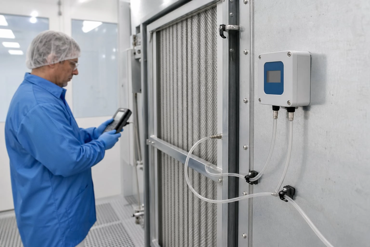
Tubing is part of the measuring system. The transmitter only reports the pressure delivered to its ports. Long, kinked, leaking, contaminated, or asymmetrical tubing can turn a stable room or filter DP into a delayed or biased signal.
Keep both pressure paths deliberate
Use tubing suited to the environment and compatible with the transmitter fittings. Route high- and low-side runs so that they are:
- As short as practical
- Protected from crushing, abrasion, and accidental disconnection
- Free of sharp bends and kinks
- Supported at intervals rather than hanging from fittings
- Clearly labeled from sensing point to instrument port
- Accessible for inspection and cleaning
- Kept separate from conditions likely to heat, cool, or damage one line differently from the other
For room-to-room DP, balanced tubing lengths can reduce the chance that one side has substantially different pneumatic response or temperature exposure. Exact equal length is not always required, but a short, open high-side line paired with a long low-side line containing restrictions is a poor arrangement.
Understand response-time effects
Tubing volume and restriction can slow the pressure signal. This matters when DP is used for tight control, rapid alarms, or fan-proving interlocks.
In simple terms:
- Longer tubing increases enclosed volume.
- Smaller inside diameter increases flow resistance.
- Dust, water, or a pinched tube increases resistance further.
- The pressure at the sensor then changes more slowly than pressure at the monitored point.
The resulting delay can cause unstable control tuning, late alarms, or disagreement between a portable reference measurement and the installed transmitter. Do not attempt to fix a mechanically slow pressure path solely by changing controller filtering or alarm delays.
Avoid accidental cross-connections
A frequent commissioning error is connecting both ports to the same pressure zone, reversing ports, or connecting one port to an unintended reference. Label both the wall ports and transmitter ports as HIGH and LOW, including the expected normal sign.
For filter applications, maintain the same labeling convention on every similar air-handling unit. A consistent convention reduces troubleshooting time when technicians compare trends across equipment.
Manage condensation, dust, and pressure-port location
Pressure sensing points should represent the intended static pressure, not velocity pressure, fan discharge turbulence, water accumulation, or a local obstruction. Good transmitter selection cannot compensate for poor pressure-port location.
Select representative pressure locations
For duct and filter DP measurements, avoid placing a pressure pickup where airflow impinges directly into the opening. A pickup exposed to high velocity or turbulent flow may include changing velocity effects rather than stable static pressure.
For room-pressure measurement, avoid locations dominated by:
- Supply diffuser jets
- Return grilles
- Door sweeps and frequently opened doors
- Exhaust capture hoods
- Fan-coil discharge patterns
- Exterior wind effects, if comparing a room to outdoors
Use a location that represents the maintained pressure relationship over the space, and evaluate the reading during realistic airflows and occupancy conditions.
Prevent water and particulate contamination
Condensation and dust are major causes of low-DP measurement error because a small amount of blockage can create a substantial restriction relative to the available pressure difference.
Control the risk by:
- Avoiding low points that can trap water
- Routing tubing so liquid does not drain into the transmitter
- Using suitable protective measures at dirty sensing locations where the application requires them
- Inspecting filter-monitoring tubing when filter dust or maintenance activity can enter ports
- Keeping open reference ports away from washdown, splashing, and airborne debris
- Checking both ports after construction, duct cleaning, or ceiling work
Do not blow high-pressure shop air into a low-DP transmitter to clear a line unless the instrument documentation explicitly permits that method. Isolate the transmitter first when using an external cleaning method, and verify the line is clear before reconnecting.
A plugged low-side line in a room-pressure application can make the reading appear persistently positive or slow to respond. A leaking high-side line may make a positive room appear neutral or negative. Either condition can defeat a control sequence while the displayed value still appears credible.
Evaluate zero drift, temperature effects, and stability
Zero is the output when both ports experience the same pressure. In low differential-pressure HVAC cleanroom measurement, zero condition is often more important than span calibration because normal operating values can be close to zero.
Zero drift can be operationally significant
Zero drift is a change in indicated DP when actual DP remains unchanged. Sources include sensor behavior over time, ambient temperature variation, mounting stress, power-supply conditions, and pressure-port contamination.
Suppose a room-pressure alarm is set at +0.01 in. w.c. If the combined zero offset and noise are of similar magnitude, the system may alarm intermittently even when the actual room pressure is stable. Widening the alarm band may reduce nuisance alarms, but it also reduces sensitivity to a real loss of pressurization. The better solution is to evaluate the complete measurement uncertainty and improve the installation where needed.
Temperature is not only an ambient concern
Temperature effects can arise from:
- Transmitter ambient temperature changes
- One tubing run routed near a warm duct or cold exterior surface
- Direct sunlight or radiant heat on a wall-mounted instrument
- Seasonal differences between the controlled room and reference area
- Warm-up behavior after power is applied
Check the stated operating temperature range and accuracy conditions for the specific transmitter. If the installation environment differs materially from the reference conditions, account for any published temperature coefficient or additional error term.
For critical room-pressure control, observe the zero and operating reading through expected temperature transitions rather than evaluating only at one stable indoor condition.
Stability is a system property
A stable displayed value is not automatically an accurate value; it can also be the result of a blocked line. Conversely, a noisy reading is not automatically a defective transmitter; it may reflect actual room disturbances, turbulent pickup location, fan pulsation, or an overly fast unfiltered input.
Investigate stability in this order:
- Confirm both pressure paths are open and correctly connected.
- Inspect tubing for damage, condensate, and contamination.
- Verify pressure-port locations are representative.
- Compare the signal during known operating events.
- Check zero with both ports exposed to the same stable pressure, using the manufacturer’s approved procedure.
- Review controller filtering, scaling, and alarm delay after mechanical issues are resolved.
Commission the loop and verify alarm behavior
Commissioning should prove the measured pressure relationship and the system response. A transmitter that passes a bench check may still fail the installed application because the tubing, ports, controller scaling, and alarm logic have not been validated together.
Commissioning sequence
- Verify documentation. Confirm the tag, intended service, units, calibrated range, output type, high/low port assignment, and applicable wiring diagram.
- Inspect the physical installation. Check tubing route, fittings, labels, mounting, port protection, and access for future service.
- Confirm zero. With both ports at the same stable pressure, check whether the indicated value is within the allowable installed zero tolerance. Follow the instrument manufacturer’s approved zero-adjustment procedure.
- Apply a known differential pressure. Use a suitable reference method or calibrated test device for the required confidence level. Test several points, including values near operational alarms or control setpoints.
- Check output scaling. Confirm that the local indication, analog signal, controller engineering units, trend display, and alarm values all represent the same DP and sign.
- Test normal process response. Observe the signal during fan operation, damper movement, or a controlled room-pressure change.
- Test alarm logic. Verify setpoint, deadband, delay, latching behavior, annunciation, and reset action.
- Test failure response. Where the system design requires it, simulate a disconnected tube, blocked sensing point, loss of power, or out-of-range input using approved site procedures.
- Record baseline values. Record clean-filter DP, normal room DP, zero check results, reference test values, alarm settings, and tubing condition.
Verify alarms at the process condition, not only electronically
An alarm that activates when a simulator drives the controller input does not prove that the sensing ports and tubing will detect a real process event. When practical and safe, test the alarm using a controlled physical change relevant to the application.
For a filter alarm, that may mean confirming the alarm logic against a known applied DP rather than waiting for a filter to load. For room pressure, it may mean observing response to an approved change in supply, exhaust, or a controlled opening at the pressure boundary. Avoid tests that compromise contamination control, safety, or facility operation.
Use delays and deadbands intentionally. Short-lived door openings can cause real room DP excursions that do not warrant a maintenance response, while a prolonged loss of differential pressure may require prompt action. The appropriate logic depends on the facility’s control narrative and risk assessment.
Use a maintenance and diagnostics checklist
Low-DP instruments benefit from focused maintenance because the main failure modes are often external to the sensing element.
Routine maintenance checklist
- Compare the current value with the established operating baseline and recent trend.
- Inspect high- and low-side tubing for kinks, loose fittings, cracks, discoloration, and unsupported sections.
- Check sensing ports for dust, paint, insulation fibers, moisture, or accidental blockage.
- Confirm the transmitter enclosure and wiring remain secure and dry.
- Verify labels still identify the measured locations and port direction.
- Perform a zero check using the approved procedure and a stable equal-pressure condition.
- Verify alarm setpoints, delays, and controller scaling after control-system changes.
- Recheck filter DP after filter replacement; a new baseline is expected.
- Document test method, reference device identification where used, as-found reading, as-left reading, and corrective action.
Diagnostic guide
| Symptom | Likely causes to investigate | First checks |
|---|---|---|
| Reading remains near zero | Both ports connected to same pressure, blocked tubing, failed fan, wrong range, lost signal scaling | Trace tubing, verify port locations, check output and controller units |
| Reading has the wrong sign | High and low ports reversed, controller sign inversion | Confirm physical connections and software scaling |
| Reading changes slowly | Long or restricted tubing, trapped condensate, plugged port, excessive filtering | Inspect and clear the pressure path; review filtering afterward |
| Reading is noisy | Turbulent port location, fan pulsation, loose tubing, unstable room condition, electrical noise | Inspect installation and correlate with equipment events |
| Repeated nuisance alarms | Zero offset, threshold too close to noise, unsuitable delay, real transient events | Perform zero check, review trend data and alarm logic |
| Reading is stable but disagrees with reference | Reference taken at a different location, plugged line, port-location bias, scaling error | Verify equivalent measurement points and inspect both tubing paths |
| Sudden filter DP change | Filter condition change, access panel open, tubing disconnected, sensing port blocked | Inspect equipment condition and pressure connections before replacing the transmitter |
Practical specification and field-work checklist
Use this checklist for a datasheet review, request for quotation, installation package, or commissioning plan:
- Measurement purpose: filter loading, airflow proving, room pressure, or another defined DP relationship.
- Normal DP range, alarm thresholds, control band, and expected transient extremes stated in in. w.c. or Pa.
- High- and low-side sensing locations identified on drawings.
- Required measurement range selected for both resolution and transient margin.
- Static pressure and differential overpressure limits confirmed for actual equipment conditions.
- Accuracy basis, zero stability, temperature effects, response behavior, and output resolution reviewed near the critical threshold.
- Process-air, moisture, dust, and cleaning-environment compatibility confirmed.
- Output signal, supply power, controller input, engineering units, and fault handling defined.
- Tubing material, routing, support, labeling, drain strategy, and access requirements specified.
- Pressure-port locations checked for static-pressure representation and protection from contamination.
- Commissioning test points, zero procedure, reference method, acceptance criteria, and alarm tests included in the work pack.
- Baseline readings and maintenance intervals recorded at turnover.
For applications requiring a transmitter selection review, compare the needed range, pressure limits, output, and installation arrangement against available differential-pressure transmitter options, compact differential-pressure instruments, or pressure measurement products for HVAC control integration. Confirm the current product documentation for the exact configuration and performance terms before final specification.
References and further reading
- ISO/TC 209 cleanroom standards catalogue for cleanroom classification, monitoring, and test methods.
- ASHRAE standards and guidelines for HVAC system design, ventilation, and control context.
- JCGM measurement uncertainty publications for reporting uncertainty and measurement results.