
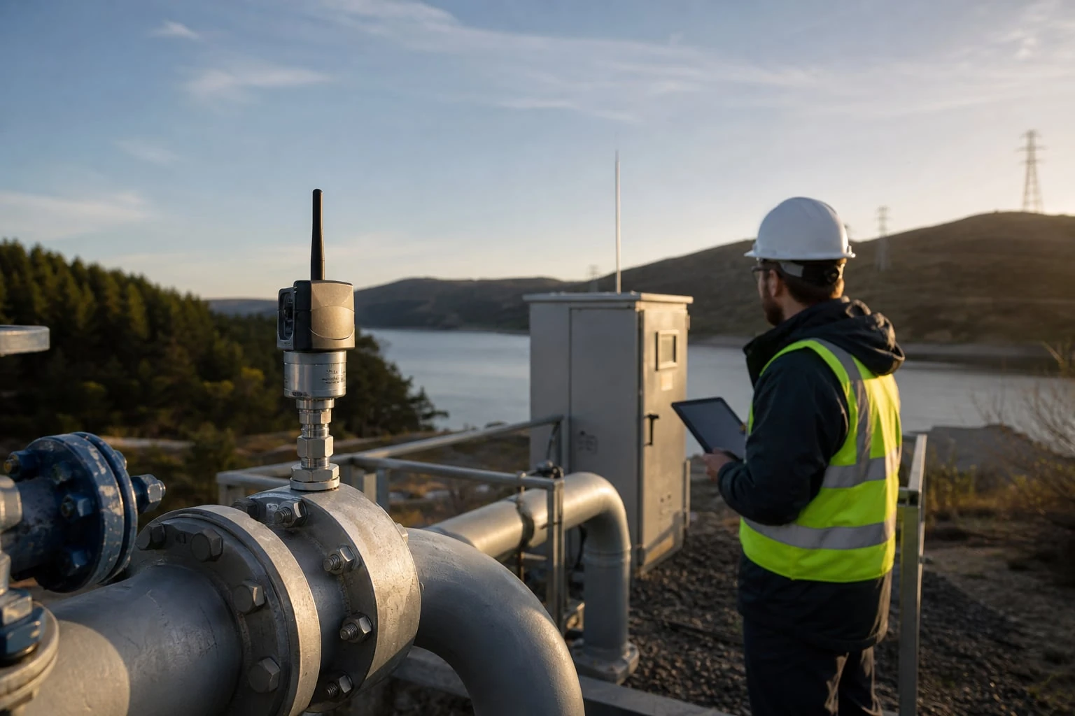
Wireless industrial sensor battery life is determined less by the battery label than by the complete duty cycle: measurement time, radio transmissions, retries, temperature, network coverage, and maintenance policy. A sensor that samples frequently but sends concise summaries may operate very differently from one that reports every reading immediately.
Specify the measurement response requirement first, then make the battery calculation transparent. The resulting design should show what happens when coverage worsens, alarms occur, or the device cannot reach the network—not just its estimated life under ideal conditions.
Define the measurement and response requirement
Start with the process decision the measurement point must support. “Monitor pressure remotely” is not enough to select a sensor, battery, or network. Define the measured variable, expected operating range, acceptable installed uncertainty, response time, and consequences of a delayed or missing reading.
For each wireless point, document the following:
- Measured variable: Pressure, temperature, differential pressure, level, or another process condition.
- Process range: Normal operating range, expected excursions, and maximum credible limit.
- Required measurement uncertainty: The uncertainty allowed for the complete installed point, including sensor performance, mounting effects, thermal effects, and any conversion or scaling.
- Decision latency: The longest acceptable time between a process change and an operator, controller, or maintenance system receiving actionable information.
- Availability need: Whether missed reports are merely inconvenient or create a safety, quality, environmental, or equipment-protection concern.
- Operating environment: Ambient temperature range, vibration, moisture exposure, electrical noise, obstructions, and accessibility.
- Data destination: A local gateway, historian, cloud platform, SCADA system, maintenance application, or OEM equipment controller.
Sensor accuracy and total installed measurement uncertainty are not the same. A pressure transmitter can have a stated accuracy under defined reference conditions while the installed reading is affected by impulse lines, mounting orientation, temperature gradients, process connection issues, or configuration errors. Battery-powered wireless operation adds another practical concern: the device may measure correctly but fail to deliver the result within the required time.
A useful requirement statement might read:
Measure suction pressure from 0 to 150 psig. Detect a 15 psig drop within 10 minutes. Provide a normal trend value every 15 minutes. Retain readings during a communications outage and identify missing or delayed data after recovery.
This requirement separates normal monitoring from abnormal response. It also gives the designer a basis for selecting sample intervals, transmission behavior, and local data storage.
Classify the point by response need
Not every point needs the same reporting architecture.
| Measurement role | Typical response need | Design implication |
|---|---|---|
| Asset condition trend | Hours to days | Long report interval and summarized data may be suitable |
| Maintenance diagnostic | Minutes to hours | More frequent samples, local history, and reliable time stamps matter |
| Process optimization | Minutes | Stable periodic delivery and known latency are important |
| Equipment protection input | Seconds or less | Confirm whether a battery wireless path is appropriate; local hardwired protection may be necessary |
| Regulatory or custody-related record | Application-specific | Define record retention, traceability, time synchronization, and validation requirements separately |
Do not assume that wireless should replace every wired signal. Where a fast trip or continuously available control input is required, a wired loop or a locally independent protection device may be the more defensible design.
Separate sampling, logging, and reporting intervals
Three intervals are often mistakenly treated as one. Keeping them separate is one of the most effective ways to meet both response and battery-life goals.
- Sampling interval: How often the sensor takes a measurement.
- Logging interval: How often a reading is stored in local memory.
- Reporting interval: How often data is transmitted through the network.
For example, a temperature device could sample every 60 seconds, log a five-minute average, and report a 15-minute trend packet. If it detects a high-temperature condition, it can transmit immediately and temporarily report more often. This arrangement can preserve process visibility without requiring a radio transmission every minute.
Choose intervals from process behavior
The sampling interval should be short enough to observe the process change of interest. The reporting interval should be short enough to support the required response time after allowing for network delay and retries.
For a slowly changing tank level, reporting every 30 minutes may be adequate. For a compressor discharge temperature that can rise quickly during a fault, a 30-minute report may be too slow even if the normal trend is smooth.
Use the fastest credible process event—not only normal process variation—to select the alarm approach. Then decide whether the device needs:
- A fixed high or low threshold,
- A rate-of-change alarm,
- A deviation from normal operating behavior, or
- A combination of these.
A common mistake is sampling only at the normal reporting interval. If a sensor wakes every 30 minutes, measures once, and transmits, it cannot reliably detect a short excursion that begins and ends between wakeups.
Use exception reporting deliberately
Exception reporting means a device sends extra messages when a configured condition is met. It can improve alarm responsiveness, but it must be included in the energy budget.
Define:
- The threshold and deadband to prevent repeated notifications near a limit;
- The maximum alarm transmission rate;
- Whether an alarm is acknowledged by the network;
- Whether the device continues sending the alarm until receipt is confirmed;
- The reset condition for returning to normal reporting; and
- What occurs if the alarm occurs during a network outage.
Avoid an alarm design that sends on every minor fluctuation. A noisy process signal, an undersized deadband, or an improperly filtered reading can create repeated transmissions and greatly reduce estimated battery life.
Build a transparent battery energy budget
A battery-life claim is meaningful only when its assumptions are visible. Estimate average current from each operating state, calculate expected consumption, and then include real-world margins for temperature, self-discharge, network retries, and alarm activity.
The basic relationship is:
I_avg = (Σ (I_n × t_n)) / (T)
Where:
I_avg= average current in milliamps (mA)I_n= current during operating staten, in mAt_n= time spent in that state during the calculation periodT= total time in the same period
A simplified battery-life estimate is:
Life_hours = fracC_usableI_avg
Where:
Life_hours= estimated service life in hoursC_usable= usable battery capacity in milliamp-hours (mAh) under the actual load and temperature conditionsI_avg= calculated average current in mA
This is an estimate, not a guarantee. Usable capacity can be lower than nominal capacity because of low temperature, pulse-current demand, battery age, voltage cutoff, and the device’s ability to use the battery across its discharge range.
Illustrative energy calculation
Assume a wireless sensor has the following daily activity:
- Sleep current: 0.015 mA for 23.95 hours per day
- Measurement activity: 8 mA for 30 seconds per day
- Radio transmission and network transaction: 55 mA for 20 seconds per day
Convert seconds to hours:
- 30 seconds = 0.0083 hours
- 20 seconds = 0.0056 hours
Daily consumption is:
(0.015 mA × 23.95 h) + (8 mA × 0.0083 h) + (55 mA × 0.0056 h)
= 0.359 + 0.066 + 0.308 = 0.733 mAh/day
The average current is:
0.733 mAh/day ÷ 24 h/day = 0.0305 mA
If an application assumed 12,000 mAh of usable capacity, the idealized result would be:
12,000 mAh ÷ 0.0305 mA = 393,443 hours
or approximately 45 years. That answer is clearly not a valid field-life prediction because the simplified activity model omits important limits: battery calendar life, temperature, device voltage requirements, extra network activity, self-discharge, and the difference between nominal and usable capacity. The example demonstrates why an energy budget must be reviewed as an engineering model rather than used as a marketing number.
A more credible planning calculation applies a conservative usable-capacity assumption and explicitly models expected transmissions, retries, alarms, and environmental conditions. Confirm the battery chemistry, nominal capacity, expected temperature range, peak-current behavior, replacement procedure, and end-of-life indication from the device documentation.
Include the events that shorten life
The following can materially change a wireless industrial sensor battery-life estimate:
- Weak signal causing longer transmissions or repeated connection attempts;
- Network registration or reconnection events;
- Confirmed-message acknowledgments;
- Uplink retries after failed delivery;
- Downlink listening windows or frequent remote configuration;
- High-rate reporting while an alarm remains active;
- Local display use, if applicable;
- Cold-weather operation;
- Firmware updates or diagnostics;
- Long communications outages with repeated reconnect attempts.
Model normal behavior and adverse behavior separately. A design that has acceptable life only with a perfect radio path is not robust enough for a remote industrial installation.
Compare cellular, LPWAN, and private radio constraints
Network choice affects battery consumption, coverage work, recurring costs, integration architecture, and who controls the data path. “Wireless” describes the connection method, not the operational design.
| Network approach | Useful fit | Battery-life considerations | Key constraints to evaluate |
|---|---|---|---|
| Cellular | Widely distributed assets without local network infrastructure | Connection setup, retries, and payload frequency can increase energy use | Carrier coverage at the installed location, service lifecycle, antenna placement, plan administration, and indoor signal loss |
| Public LPWAN | Low-data-rate monitoring across an available public network | Often suited to small, infrequent messages, subject to device and network behavior | Confirm coverage at the actual asset, message limits, data routing, device onboarding, and service continuity |
| Private LPWAN | Facilities needing local ownership of gateways and data paths | Can support low-power periodic measurements when designed for the site | Gateway placement, backhaul, capacity, interference, network administration, and spare hardware |
| Private industrial radio/mesh | A defined plant or equipment area with local infrastructure | Relay behavior, listening time, and routing can affect each node differently | Network topology, power availability at repeaters, line of sight, interference, and maintenance responsibility |
Cellular can simplify deployment for isolated equipment, but a coverage map is not an installation survey. A device may have adequate outdoor service yet struggle inside a metal enclosure, basement, pump house, or equipment skid.
Private networks provide more control over gateway placement and data ownership, but that control creates operating responsibilities. Someone must maintain gateways, backhaul connections, credentials, firmware versions, and configuration backups.
Match payload and reporting behavior to the network
A low-power network is usually best suited to concise, purposeful data. Sending one scaled value, a device status, battery state, signal diagnostic, and an alarm code is materially different from sending high-frequency raw waveform data.
Before selecting a network, determine:
- Payload size per report;
- Normal reports per day;
- Alarm reports per day in a plausible upset;
- Required acknowledgment behavior;
- Local storage depth during outage;
- Required delivery latency;
- Whether remote configuration or firmware maintenance is expected; and
- Integration method for the owner’s SCADA, historian, or cloud environment.
Data ownership is a design requirement. Identify who can access raw measurements, configuration history, alarm records, device identities, and exported data if a network service, gateway, or equipment supplier changes.
Survey coverage, antenna placement, and enclosure effects
Radio coverage must be checked at the final sensor mounting point, with the intended antenna, enclosure, process equipment, and surrounding structures in place. A successful test at ground level or outside an enclosure does not prove reliable operation at the installed position.
Metal tanks, structural steel, cabinets, pipe racks, concrete walls, wet vegetation, and moving equipment can attenuate or reflect radio signals. The installed environment can also change over time as doors are closed, equipment is added, or process vessels are filled.
Conduct a practical site survey
A useful survey process includes:
- Mark the exact measurement-point location and expected antenna location.
- Test at normal and unfavorable operating positions where practical.
- Record signal diagnostics, packet success, latency, and retry count—not only a pass/fail indication.
- Evaluate antenna orientation and separation from large conductive surfaces.
- Check routing of antenna cables, if used, for damage risk and water ingress.
- Test the intended gateway or cellular service path from the final installation position.
- Repeat testing after enclosure doors, covers, or access panels are closed.
- Document the results with photographs and location identifiers.
Antenna placement should protect the antenna without burying it inside a conductive enclosure. External mounting can improve the radio path, but it introduces mechanical exposure and cable-entry risks. Confirm enclosure integrity, strain relief, grounding practices where applicable, and the allowable antenna arrangement for the device.
Do not place a sensor solely where the radio signal is strongest. The process connection must remain representative, accessible for maintenance, and protected from damage. The correct installation balances measurement quality, radio reliability, and maintainability.
Design alarms, retries, buffering, and data recovery
A reliable measurement system plans for communication loss. The sensor should not silently discard the distinction between “no change occurred” and “a reading was not delivered.”
Define the outage behavior before procurement:
- How many readings can be stored locally?
- Are stored records time-stamped at measurement time or at transmission time?
- Is the buffer first-in-first-out, or does it preserve alarms preferentially?
- Does the device automatically backfill data after reconnection?
- Does backfill create a large, short-term energy demand?
- How is a gap identified when storage capacity is exceeded?
- Does the host system distinguish delayed readings from current readings?
Set retry behavior around the process need
Retries improve delivery probability but consume energy. A reasonable retry plan sets a maximum number of attempts, a spacing interval, and a transition to a lower-energy recovery mode.
For example, an asset condition point may attempt a limited number of retransmissions, store the record locally, and wait until the next scheduled report. A high-priority alarm may use a more persistent sequence, but the maximum alarm activity should still be bounded so a prolonged network outage does not rapidly exhaust the battery.
Use sequence numbers, event timestamps, and quality indicators where the system supports them. These fields make it possible to identify duplicates, delayed packets, missing data, and recovered records.
Plan cybersecurity, provisioning, and lifecycle maintenance
A wireless sensor is an operational asset and a connected endpoint. Its lifecycle plan should cover identity, access, configuration, replacement, and retirement.
At minimum, define:
- Device identity: A unique identifier tied to the physical asset and its records.
- Credential handling: Who provisions credentials, where they are stored, and how access is controlled.
- Authorization: Which users or systems may read data, change configuration, or initiate maintenance actions.
- Configuration control: A record of engineering units, range, alarm thresholds, reporting intervals, and firmware version.
- Data path ownership: The owner of gateway, cellular account, application account, and historical data.
- Replacement process: How a replacement device is provisioned, verified, and associated with the same asset record.
- Decommissioning: How credentials and network access are removed when equipment is retired.
Avoid shared default credentials, undocumented configuration changes, and “orphaned” devices that remain registered after removal from service. Also confirm whether battery replacement retains settings, time, stored data, and network enrollment—or whether re-provisioning is required.
For applications that need documented quality practices from an instrument supplier, verify the product-specific documentation and service process. WKSENSOR states that its published quality system includes incoming inspection, serialized units, a 24-hour powered aging cycle, multi-point calibration, and final inspection; confirm what documentation applies to the exact instrument and order.
Use a wireless site acceptance checklist
Use this checklist for a datasheet review, request for quotation, factory configuration review, or field acceptance package.
Measurement and installation
- Process variable, range, engineering units, and required installed uncertainty are defined.
- Sensor accuracy is evaluated separately from installation effects and process-connection effects.
- Normal reporting interval and maximum alarm-response time are specified.
- Sample, logging, and reporting intervals are separately documented.
- Alarm thresholds, deadbands, delays, and reset behavior are defined.
- The mounting point is representative of the process and accessible for inspection or replacement.
- Ambient temperature, vibration, moisture, and enclosure conditions are checked against product documentation.
Power and communications
- Battery-life estimate lists battery assumptions, normal message rate, alarm activity, and retry behavior.
- Cold-temperature and poor-coverage effects are considered.
- Network option is selected based on coverage, latency, data ownership, and maintenance responsibility.
- Coverage testing is performed at the final installed location.
- Antenna placement, cable routing, enclosure effects, and physical protection are documented.
- Expected signal diagnostics and acceptable retry behavior are recorded at commissioning.
Data, recovery, and lifecycle
- Data destination, ownership, retention, and system integration method are identified.
- Local buffer depth, timestamps, backfill behavior, and gap handling are confirmed.
- Device identity, credentials, authorized users, and configuration records are controlled.
- Battery replacement and device replacement procedures are included in the maintenance plan.
- Commissioning records include installed location, serial number, configuration, baseline signal condition, and functional alarm test.
A wireless measurement point is ready for deployment when its battery estimate, coverage evidence, outage behavior, and maintenance ownership are all documented—not when it merely sends a successful test message. For product categories and measurement technologies relevant to a wireless instrumentation project, review the industrial instrument catalog and compare the exact product documentation with the requirements checklist above.
References and further reading
- LoRaWAN specifications for protocol behavior and network design context.
- GSMA Mobile IoT resources for cellular IoT deployment and ecosystem guidance.
- IEC 62443 overview for industrial automation and control-system cybersecurity principles.