
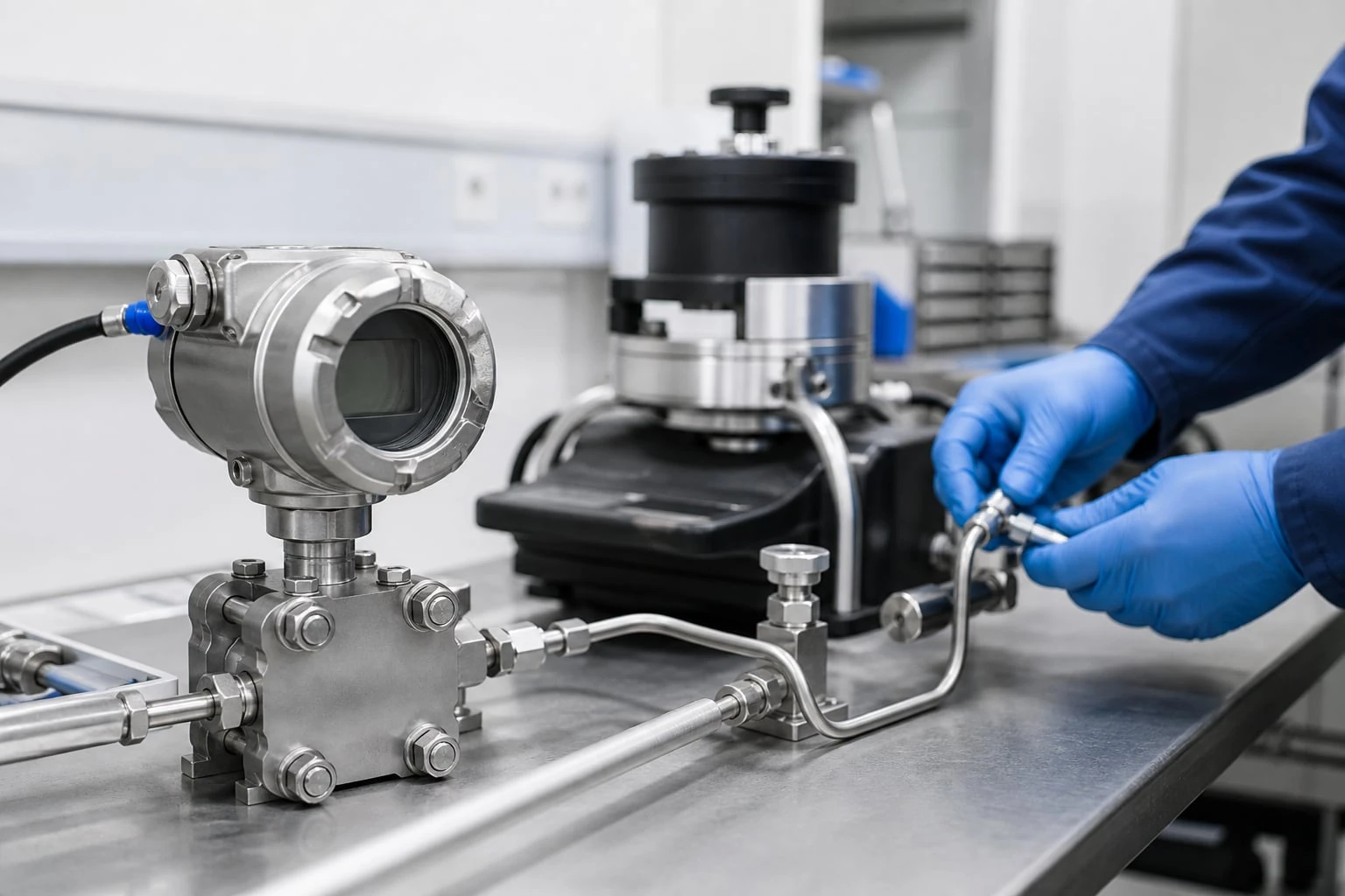
A pressure transmitter accuracy budget estimates how far the installed measurement may differ from actual process pressure under defined operating conditions. It should not be based on the transmitter’s headline accuracy alone.
A defensible pressure transmitter accuracy budget separates the instrument’s reference accuracy from temperature effects, calibrated-span or turndown effects, calibration uncertainty, drift, and installation-specific residual errors. Use a consistent basis—typically psi, % of calibrated span, or % of reading—and state whether the result is a conservative worst-case limit or a statistical estimate.
Define accuracy, error, and uncertainty before calculating
These terms are often used interchangeably, but they represent different parts of a measurement decision.
Error is the difference between the measured value and the actual pressure.
Error = indicated pressure - actual pressure
For example, if the process pressure is 50.0 psig and the transmitter indicates 50.4 psig, the error is +0.4 psi.
Accuracy is a specification describing the expected closeness of a transmitter’s output to the actual input under stated conditions. It is usually expressed as a limit, such as ±0.10% of calibrated span or ±0.10% of URL. The exact meaning depends on the manufacturer’s datasheet.
Uncertainty describes doubt about a reported measurement. Calibration uncertainty may include the uncertainty of the reference standard, resolution, repeatability, environmental variation during calibration, and the calibration method.
Reference accuracy is the transmitter’s specified performance at defined reference conditions. Those conditions commonly include a stated ambient temperature, stable supply voltage, a specified mounting position, and a defined calibration range. Reference accuracy does not automatically describe field performance.
Total probable error (TPE) is a combined estimate that may include reference accuracy plus environmental and operating effects. Manufacturers do not always define TPE in the same way. Before comparing transmitters, verify which effects are included, whether the values are statistically combined, and whether the result applies to the intended calibrated span.
A useful budget starts by defining:
- The measured pressure type: gauge, absolute, sealed gauge, or differential pressure
- Normal operating pressure, minimum pressure, and maximum pressure
- Required decision point or control tolerance
- Calibrated range and transmitter URL
- Expected ambient temperature and process temperature
- Required interval between calibrations
- Whether the budget is a worst-case limit or an estimated uncertainty
Separate reference accuracy from total probable error
Reference accuracy is a component of installed performance, not the final answer.
A datasheet may state reference accuracy as:
- Percent of calibrated span: error changes with the configured measurement span.
- Percent of URL: error is based on the transmitter’s upper range limit, regardless of the configured span.
- Percent of reading: error scales with the actual measured pressure.
- A combination of zero error and span error: common where each contribution is stated separately.
These bases are not interchangeable. Convert all items to a common unit before adding them.
For a pressure range of 0 to 100 psig:
- ±0.10% of calibrated span equals ±0.10 psi.
- ±0.10% of URL also equals ±0.10 psi if the URL is 100 psi.
- ±0.10% of reading equals ±0.05 psi at a 50 psi operating point.
If that same transmitter is configured for 0 to 25 psig while its URL remains 100 psi:
- ±0.10% of calibrated span equals ±0.025 psi.
- ±0.10% of URL remains ±0.10 psi.
This difference is why a small headline accuracy number can be misleading without its reference basis.
Two ways to combine contributors
Use one method consistently and document it.
Worst-case summation adds the absolute value of every bounded contribution:
E_worst case = |E_1| + |E_2| + |E_3| + …
This is conservative and useful where every specified limit could align in the unfavorable direction.
Root-sum-square (RSS) estimates combined error for independent, random-like contributors:
E_RSS = sqrt(E_1^2 + E_2^2 + E_3^2 + …)
RSS can be appropriate for a practical performance estimate, but only when the inputs are compatible with statistical combination. Do not apply RSS automatically to manufacturer limits that are stated as absolute bounds, systematic installation errors, or uncorrected bias.
A good practice is to report both where the application justifies it:
- A conservative worst-case measurement limit for acceptance or protection decisions
- An RSS estimate for normal operating performance, with assumptions clearly stated
Account for turndown and calibrated span
Turndown is the relationship between a transmitter’s maximum available span and the configured calibrated span.
Turndown ratio = (URL) / (calibrated span)
For a transmitter with a 300 psig URL configured from 0 to 60 psig:
Turndown ratio = (300) / (60) = 5:1
Turndown itself does not necessarily make a transmitter inaccurate. The risk comes from applying a specification expressed as a percentage of URL to a much smaller calibrated span.
To convert an error expressed as percent of URL into percent of calibrated span:
\% of span = \% of URL × (URL) / (calibrated span)
For example, a ±0.10% URL reference accuracy on a 300 psig URL is:
0.10\% × 300 psi = 0.30 psi
On a 60 psig calibrated span, that is:
(0.30) / (60) × 100 = 0.50\% of calibrated span
Before selecting a transmitter, confirm whether each stated accuracy term is based on URL, calibrated span, or reading. This is especially important for low-pressure measurement, narrow control ranges, and transmitters configured at high turndown.
Check the low end, not only full scale
A pressure measurement may satisfy an error target at its maximum operating pressure and still be unsuitable near its normal low-pressure point.
For effects stated as a percentage of reading, calculate error at the lowest important operating value. For effects stated as a percentage of span or URL, convert them to psi and compare them against the process tolerance at both low and high operating points.
For example, a fixed ±0.30 psi error may be acceptable at 200 psi but represent a large percentage of a 5 psi low-end operating point.
Quantify ambient and process temperature effects
Temperature is frequently the largest omitted item in a pressure transmitter accuracy budget.
Ambient temperature affects the transmitter electronics, sensing element, housing, and terminal assembly. Use the temperature at the transmitter body—not merely the room temperature or weather forecast.
Process temperature can affect the sensing element through the pressure connection, diaphragm, wetted parts, remote seal, capillary, impulse line, or mounting hardware. The transmitter’s body temperature may differ substantially from the fluid temperature.
Datasheets may list separate temperature effects for zero and span.
- Zero thermal effect creates an offset that is often expressed as % of URL per temperature increment.
- Span thermal effect changes sensitivity and may be expressed as % of reading, % of span, or % of URL per temperature increment.
For a zero temperature coefficient:
E_zero,temp = ((zero coefficient) / (100)) × URL × (Δ T) / (specified temperature increment)
Where:
E_zero,temp= zero shift in psi- URL = upper range limit in psi
Δ T= deviation from the stated reference temperature in °F or °C
For a span effect stated as a percentage of reading:
E_span,temp = ((span coefficient) / (100)) × P_actual × (Δ T) / (specified temperature increment)
Where P_actual is the operating pressure in psi.
Do not use a transmitter’s full allowable operating-temperature range as the expected temperature deviation unless that is genuinely the operating case. Build the budget around credible minimum and maximum temperatures at the sensor.
Also consider whether process-temperature effects are already covered by the datasheet temperature specification. Avoid counting the same effect twice, but do not assume ambient compensation also covers process heat conducted into a pressure port or seal assembly.
Temperature-related installation risks
A technically capable transmitter can still produce poor results when the installation drives sensor temperature outside the budget assumptions. Check for:
- Direct solar heating of outdoor transmitter housings
- Heat conduction from hot process piping
- Steam tracing near the pressure connection
- Cold-weather exposure and freeze risk in sensing lines
- Stratified enclosure temperatures
- Long impulse lines with changing fluid density
- Remote seals or capillaries whose temperature behavior differs from a direct-mounted transmitter
Where temperature varies over time, evaluate the budget at the temperature extremes and during startup, shutdown, and cleaning cycles—not just at normal steady operation.
Include reference standard and calibration uncertainty
A transmitter calibration adjusts or verifies the relationship between applied pressure and output. It does not remove all uncertainty.
The calibration contribution may include:
- Uncertainty of the pressure reference standard
- Resolution of the reference and transmitter readout
- Reference repeatability and stability
- Test connection leakage or pressure instability
- Hysteresis and repeatability observed during testing
- Ambient-temperature effects during calibration
- Technician method, setpoint selection, and interpolation
- As-found error, as-left error, and the acceptance tolerance
A calibration certificate can report a measured result and an uncertainty, but it is important to distinguish those from the transmitter’s field accuracy. A transmitter can be calibrated correctly at a controlled temperature and still have a larger installed error when process and ambient conditions change.
Reference standard uncertainty is not transmitter tolerance
Suppose a pressure calibrator has a stated uncertainty of ±0.03 psi under the test conditions. That does not mean the transmitter is accurate to ±0.03 psi. It is one contributor to uncertainty in the calibration result.
For a field calibration, use the actual uncertainty applicable to the range, pressure media, orientation, temperature, and time since the reference standard’s last calibration. A standard’s published best performance may not apply across its full range.
If your organization uses a test accuracy ratio or similar internal requirement, apply it to the required decision tolerance and calibration procedure. Do not substitute a generic ratio for an uncertainty analysis.
Work through an illustrative error budget
The following example is illustrative only. It uses assumed values to show the method; it is not a transmitter specification or a recommended acceptance limit.
Application assumptions
A transmitter has:
- URL: 0 to 300 psig
- Configured range: 0 to 60 psig
- Normal operating point being evaluated: 60 psig
- Reference temperature: 68°F
- Expected transmitter temperature: 98°F
- Temperature deviation: 30°F
Assumed contributors:
| Contributor | Assumed specification or allowance | Converted error at 60 psig |
|---|---|---|
| Reference accuracy | ±0.10% of calibrated span | ±0.060 psi |
| Zero temperature effect | ±0.02% of URL per 10°F | ±0.180 psi |
| Span temperature effect | ±0.03% of reading per 10°F | ±0.054 psi |
| Calibration uncertainty | ±0.05% of calibrated span | ±0.030 psi |
| Residual installation effect | Assessed allowance | ±0.100 psi |
The reference accuracy is:
0.10\% × 60 psi = 0.060 psi
The zero temperature effect is:
0.02\% × 300 psi × (30°F) / (10°F) = 0.180 psi
The span temperature effect at a 60 psig reading is:
0.03\% × 60 psi × (30°F) / (10°F) = 0.054 psi
The calibration uncertainty is:
0.05\% × 60 psi = 0.030 psi
The ±0.100 psi installation allowance could represent a documented residual effect after addressing mounting, line pressure loss, static-head correction, or other application-specific influences. It should not be inserted arbitrarily; identify its source.
Conservative worst-case result
E_worst case = 0.060 + 0.180 + 0.054 + 0.030 + 0.100
E_worst case = ±0.424 psi
As a percentage of the 60 psi calibrated span:
(0.424) / (60) × 100 = ±0.707\% of span
RSS estimate
If the contributors are treated as independent and suitable for RSS combination:
E_RSS = sqrt(0.060^2 + 0.180^2 + 0.054^2 + 0.030^2 + 0.100^2)
E_RSS ≈ ±0.223 psi
This is approximately:
(0.223) / (60) × 100 = ±0.372\% of span
The lesson is not that RSS is always preferable. It is that the stated ±0.10% reference accuracy is only a small part of this installed accuracy budget. Temperature and installation effects dominate the example.
Translate the budget into a transmitter specification
Start with the measurement requirement, then select the transmitter and installation details that keep the combined budget within the allowable error.
A practical pressure transmitter specification should state:
-
Pressure type and units
Specify psig, psia, sealed gauge, or differential pressure correctly. A gauge-versus-absolute mismatch is not an accuracy issue that calibration can fix. -
Normal, minimum, and maximum operating pressure
Set the calibrated range around the usable process range while considering pressure excursions and any applicable overpressure requirement. -
Required installed error
State the allowed error in psi, % of reading, or % of calibrated span at defined operating points. -
Required reference accuracy basis
Request the accuracy basis explicitly: % URL, % span, % reading, or a stated combination. -
Configured span and acceptable turndown
Evaluate accuracy at the actual configured span, not only at the transmitter’s maximum span. -
Ambient and process temperature envelope
Specify expected normal and extreme temperatures at the transmitter and pressure connection. -
Long-term stability and calibration interval
If the device will be operated for an extended interval between calibrations, include the applicable stability or drift allowance from the datasheet. -
Output and system compatibility
Confirm the output signal, power supply, input resolution, grounding approach, load limits, and control-system scaling. A transmitter can meet its own accuracy specification while the complete loop does not. -
Materials and process connection
Confirm pressure connection, wetted materials, pressure media compatibility, sealing method, and cleaning or contamination constraints. -
Installation conditions
Identify mounting elevation, impulse lines, vibration, pulsation, heat sources, electrical noise, and accessibility for calibration.
When comparing options, review the detailed datasheets for the applicable pressure transmitter products rather than comparing only a single accuracy figure. The relevant specification is the one that applies to the selected range, output, environmental condition, and installation arrangement.
Use a final verification checklist
Use this checklist when preparing a datasheet review, request for quotation, design review, calibration procedure, or commissioning work pack.
- Is the pressure type correct: gauge, absolute, sealed gauge, or differential?
- Are all error contributors converted to the same unit and basis?
- Is reference accuracy distinguished from total probable error?
- Does each accuracy value state whether it is based on URL, span, or reading?
- Has the actual calibrated span and turndown been evaluated?
- Has error been checked at low, normal, and maximum operating pressure?
- Are transmitter-body ambient temperatures and process-connection temperatures defined?
- Are zero and span temperature effects calculated separately when specified separately?
- Is calibration uncertainty based on the actual reference standard and field procedure?
- Are drift and the intended recalibration interval included where relevant?
- Are static head, line loss, pulsation, leaks, mounting, and process effects evaluated?
- Is the combination method identified as worst-case, RSS, or another documented method?
- Is the resulting installed error smaller than the process, control, quality, or safety decision tolerance?
- Can commissioning verify the configured range, output scaling, zero, span, loop indication, and documented as-left condition?
The final pressure transmitter accuracy budget should be retained with the instrument specification and updated if the range, mounting arrangement, process temperature, calibration method, or maintenance interval changes.
References and further reading
- JCGM 100 — Guide to the Expression of Uncertainty in Measurement for uncertainty evaluation and reporting principles.
- NIST Technical Note 1297 for expressing uncertainty in NIST measurement results.
- IEC 61298 series catalogue for performance evaluation methods used with process measurement and control devices.