
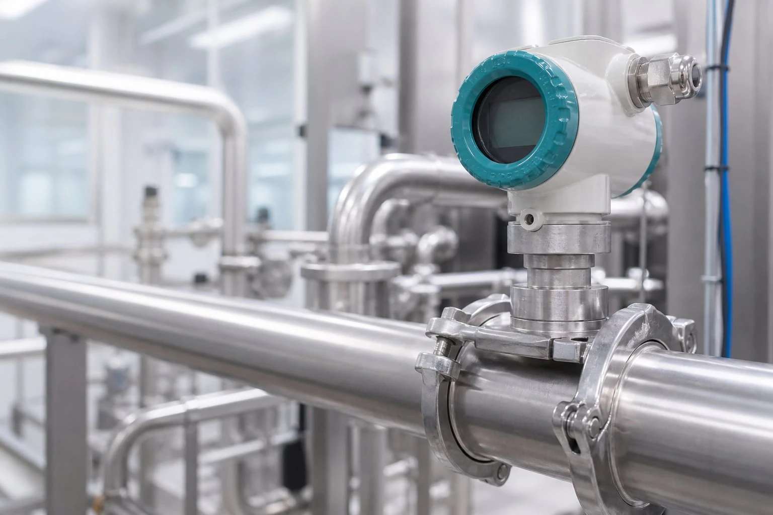
A flush diaphragm pressure transmitter is usually the right choice when the process medium can plug, harden, collect, or resist cleaning in a conventional pressure port. The sensing diaphragm sits nearly level with the process boundary, eliminating the narrow internal cavity that causes delayed response, false readings, and maintenance problems.
For a defensible flush diaphragm pressure transmitter selection, start with the medium’s failure mechanism—not just its nominal pressure and temperature. Then specify the diaphragm and sealing materials, process connection, pressure range, installation orientation, cleaning method, and calibration access as one system. A flush face prevents many plugging problems, but it does not automatically solve compatibility, thermal, mounting, or hygiene issues.
Identify When a Standard Pressure Port Becomes a Liability
A conventional pressure transmitter commonly uses a recessed pressure port: process pressure reaches the sensing element through a small bore or cavity. This design is effective for clean, low-viscosity liquids and gases. It becomes a liability when material can enter and remain in that cavity.
Choose a flush diaphragm arrangement when the process is likely to cause one or more of these conditions:
- Plugging: Fibers, pulp, slurry solids, polymer fragments, food particulates, or sediment block a small pressure passage.
- Viscous buildup: Grease, resin, paint, adhesive, syrup, wax, and heavy oils move slowly and may not clear a recessed port.
- Crystallization or curing: Salt solutions, urea-based fluids, sugar products, coatings, and reactive materials can form deposits after cooling, evaporation, or exposure to air.
- Solidification: Materials that freeze, congeal, or set at ambient temperature can trap pressure in a port after a shutdown.
- Cleaning requirements: Hygienic processes may need a smooth, drainable wetted surface with minimal product hold-up.
- Difficult maintenance access: A plugged impulse passage can require removal and cleaning; a flush diaphragm may reduce this intervention if correctly installed.
The principle is straightforward. Process pressure acts directly on a thin, wetted diaphragm. The diaphragm deflects slightly, and the transmitter converts that deflection into an electrical pressure signal. Because there is no small exposed pressure passage in front of the diaphragm, the process has fewer places to lodge.
However, “flush” must describe the installed assembly, not only the transmitter face. A flush diaphragm mounted behind a thick nozzle, within an oversized adapter, or at the end of a dead-ended branch can still accumulate product and create a measurement delay.
Classify the Medium and Failure Mechanism
A useful specification begins by classifying what the fluid can do at the sensing point. The same transmitter may be appropriate for a smooth syrup and inappropriate for a slurry containing abrasive mineral solids, even if both operate at the same pressure.
Evaluate the medium beyond its chemical name
Document the following process details:
-
Viscosity at minimum, normal, and maximum process temperature
Viscosity often changes sharply with temperature. A fluid that flows freely during operation may become paste-like during startup, shutdown, or washdown. -
Solids content, particle size, and particle shape
Fine suspended particles may settle in a branch connection. Long fibers and sticky agglomerates can bridge small openings. Hard particles may erode an exposed diaphragm. -
Crystallization, drying, curing, or polymerization behavior
Identify whether deposits form when the medium cools, loses solvent, contacts air, or remains stagnant. -
Chemical compatibility
Check the diaphragm alloy, any applied coating, process gasket or O-ring, weld materials, and—where used—remote-seal fill fluid. Compatibility must cover normal service, cleaning chemicals, sterilization conditions, and upset exposure. -
Abrasion and mechanical damage risk
A thin diaphragm improves pressure transmission but is not a wear plate. High-velocity solids, scraping tools, or direct mechanical impact can permanently alter the measurement. -
Hygienic and cleanability requirements
Determine whether the process needs a specific clamp geometry, surface finish, drainability, cleaning-in-place sequence, or documented material controls. Do not assume that a flush diaphragm alone establishes hygienic suitability.
Match the failure mechanism to the solution
| Process problem | Why a standard port fails | Flush diaphragm benefit | Remaining concern |
|---|---|---|---|
| High viscosity | Material does not move through a narrow bore | Direct pressure exposure reduces trapped volume | Ensure the mounting nozzle is also short and flush |
| Crystallizing fluid | Crystals form in a cooled or stagnant port | Fewer sheltered surfaces for crystal growth | Consider temperature control and cleaning frequency |
| Fibrous or particulate slurry | Solids bridge or pack into the pressure path | No small front-end passage to plug | Abrasion and diaphragm impact may still occur |
| Sticky or curing material | Deposit changes the pressure transfer path | Smooth exposed face is easier to clean | Verify cleaning method will not damage the diaphragm |
| Sanitary liquid or paste | Dead legs retain product and cleaning residue | Suitable connections can minimize hold-up | Validate gasket compression, drainability, and cleaning process |
| Hot process with transmitter kept away from heat | Direct-mounted electronics may exceed limits | A remote seal can move the transmitter body away | Fill-fluid temperature effects must be evaluated |
The key distinction is between deposit prevention and deposit tolerance. A flush face is generally more deposit-tolerant than a recessed port, but it cannot prevent a coating from forming on the diaphragm. If buildup is unavoidable, the installation must support cleaning, inspection, and repeatable zero verification.
Compare Flush Diaphragm and Remote Seal Arrangements
A direct-mounted flush diaphragm transmitter and a remote diaphragm seal both isolate the sensing system from difficult media. They solve different installation problems.
A direct flush diaphragm transmitter places the sensing diaphragm at the transmitter’s process connection. A remote seal system uses a process diaphragm connected to the transmitter by a filled passage, commonly through a capillary tube. Pressure moves through the fill fluid to the transmitter sensor.
| Selection factor | Direct flush diaphragm transmitter | Remote diaphragm seal system |
|---|---|---|
| Response time | Typically faster because the pressure path is short | May be slower due to fill-fluid volume and capillary length |
| Temperature at electronics | Electronics remain close to the process connection | Transmitter can be located farther from hot or cold equipment |
| Installation simplicity | Usually simpler and more compact | Requires capillary routing and protection |
| Temperature-induced shift | Lower system complexity, but process temperature still affects zero | Fill-fluid expansion and capillary temperature gradients can create additional shift |
| Cleaning exposure | Transmitter is close to the cleaning zone | Seal can remain at process while transmitter is located elsewhere |
| Mechanical risk | Body may be exposed to vibration, washdown, or heat | Capillary can be kinked, crushed, or damaged |
| Maintenance | Fewer components | More components and more installation variables |
Use a direct flush diaphragm transmitter when the process temperature, access, vibration, and mounting location are compatible with the transmitter’s published limits. This arrangement is generally easier to install and troubleshoot.
Use a remote seal when the transmitter electronics must be separated from the process because of temperature, access, vibration, or physical space. Remote seals are also common when a specialized process connection is needed at the vessel but the transmitter must be mounted at a more accessible location.
Do not specify a remote seal simply because the fluid is viscous. A capillary system introduces its own uncertainty sources. Confirm the permitted capillary length, elevation arrangement, process temperature range, ambient temperature range along the capillary, fill-fluid compatibility, and expected thermal zero shift with the supplier.
Select Diaphragm, Coating, Seal, and Fill Materials
Material selection is a wetted-system decision. The diaphragm is important, but it is not the only component exposed to the process.
Diaphragm construction and coatings
A metallic diaphragm is commonly selected for strength, weldability, and broad industrial chemical resistance. The correct alloy depends on the actual chemistry, concentration, temperature, cleaning agents, and contaminants. A material that tolerates a process liquid at room temperature may corrode or pit during a hot cleaning cycle.
A coated diaphragm may be considered when the base alloy needs added resistance to corrosion, sticking, or abrasion. But a coating introduces additional questions:
- Can the coating withstand the full pressure and vacuum range without damage?
- Is it resistant to the process and cleaning chemicals?
- Can it tolerate abrasive solids or repeated cleaning?
- Will the coating alter response, temperature behavior, or long-term stability?
- Can the user inspect it for damage without removing the transmitter?
Do not treat a coating as a universal upgrade. In abrasive service, a damaged coating may create a concentrated corrosion or contamination risk.
Process gaskets and elastomeric seals
For clamp, flange, and threaded connections, the gasket or O-ring can be the limiting material. Specify its compatibility with:
- Process chemistry and concentration
- Maximum continuous and cleaning temperature
- Vacuum conditions
- Pressure and extrusion risk
- Required cleaning chemicals
- Hygienic or contamination-control requirements
Compression also matters. An under-compressed gasket can leak or admit air. Over-compression can distort the gasket, damage an elastomer, or create an undesirable internal geometry.
Fill fluid for remote seals
Remote seal systems use fill fluid behind the isolation diaphragm. That fluid must remain stable and compatible with the expected operating temperatures. Its thermal expansion contributes to zero shift, particularly when the process diaphragm, capillary, and transmitter experience different temperatures.
For a remote system, ask for the expected installed performance over the actual process and ambient temperature envelope—not only the transmitter’s standalone reference accuracy.
Match Clamp, Thread, and Flange Process Connections
The pressure connection must create a reliable seal while preserving the reason for choosing a flush diaphragm: an unobstructed, cleanable pressure boundary.
Clamp connections
Sanitary clamp connections are often used where rapid disassembly and cleaning access matter. They can support a smooth process-facing installation when the matching ferrule, gasket, and clamp are correctly selected.
Confirm:
- Nominal clamp size and mating geometry
- Gasket material and profile
- Maximum pressure and temperature for the complete assembled connection
- Alignment of the transmitter face and vessel ferrule
- Whether the installed joint creates a step, pocket, or gasket intrusion
- Whether the connection remains accessible for inspection and tightening
A clamp connection is not automatically hygienic merely because it uses a sanitary-style fitting. The full installed geometry and cleaning method must be suitable for the process.
Threaded connections
Threaded process ports are compact and familiar, but they can introduce crevices and dead volume. For viscous or hygienic service, a threaded adapter may defeat an otherwise flush diaphragm design if the diaphragm sits recessed from the vessel interior.
When a threaded flush connection is necessary, verify the required mating port geometry, thread engagement, sealing method, torque, and final diaphragm position. Do not use thread sealant in a way that can migrate into the process or interfere with seating.
Flanged connections
Flanges are useful for larger nozzles, higher mechanical loads, vessel connections, and installations where a gasketed face is preferred. They also allow a diaphragm seal to be built into a geometry suited to the vessel nozzle.
Specify the flange facing, size, pressure-temperature rating, gasket type, bolt material, and bolt-tightening procedure as part of the mechanical design. The transmitter or seal assembly must be supported so piping loads and vibration are not carried by the diaphragm connection.
Evaluate Temperature Effects, Orientation, and Zero Shift
A transmitter’s stated accuracy is not the same as total installed measurement uncertainty. Installation geometry, temperature, static head, deposits, and calibration conditions can all shift the reading.
Separate instrument accuracy from installed error
A simplified uncertainty model can be written as:
U_installed = sqrt(U_sensor^2 + U_cal^2 + U_random^2)
Where:
U_installedis the estimated combined uncertainty.U_sensoris the transmitter’s stated uncertainty under its reference conditions.U_calis uncertainty from the calibration reference and method.U_randomrepresents other independent random effects.
This root-sum-square approach is only appropriate for independent, random terms expressed on a comparable basis. Systematic effects—such as a hot remote-seal capillary, diaphragm coating, or a static liquid head—should be estimated separately and corrected or included as a stated bias. They should not be hidden inside a generic accuracy figure.
Account for static head
If the transmitter is mounted below a liquid pressure reference point, the liquid column adds pressure. For water-like fluids, an illustrative calculation is:
Δ P = 0.433 × SG × h
Where:
Δ Pis pressure difference in psi.SGis specific gravity relative to water.his vertical liquid height in feet.
For example, assume a process liquid has SG = 1.20, and the transmitter diaphragm is 6 ft below the desired measurement elevation:
Δ P = 0.433 psi/ft × 1.20 × 6 ft = 3.12 psi
This is an illustrative static-head offset, not a universal correction. Density may change with temperature or composition, and vessel geometry may affect the actual reference level.
Consider orientation and thermal exposure
Mount the diaphragm where it will see representative process pressure without trapping gas, sediment, or cleaning solution. For liquid service, avoid locations where gas can collect against the diaphragm. For slurry service, avoid dead-ended branches where solids settle. For gas service, prevent condensate from collecting at the sensing point.
Temperature can cause zero shift through several mechanisms:
- Sensor and electronics temperature effects
- Diaphragm stress caused by temperature changes
- Changing process density and static head
- Deposits that form or release as temperature changes
- Fill-fluid expansion in remote seal systems
- Uneven heating of capillaries, adapters, or vessel nozzles
If a process has startup-to-operating temperature swings, establish zero with the system in a defined condition. A zero set at ambient temperature may not remain valid at process temperature.
Plan Cleaning, Installation, and Calibration Access
A flush diaphragm should be easy to inspect, clean, isolate, and verify. These requirements should be addressed before equipment fabrication, not after a recurring fouling issue appears.
Installation practices that protect the measurement
- Mount the diaphragm level with the vessel or pipe interior whenever the connection design allows.
- Keep adapters and nozzles short enough to avoid creating a product pocket.
- Avoid diaphragm locations directly exposed to aggressive impingement, pump pulsation, or mechanical scraping unless the assembly is designed for that duty.
- Support the transmitter and connected conduit so mechanical load is not transmitted through the process connection.
- Protect remote capillaries from crushing, kinking, vibration, and localized heat sources.
- Use a mounting location that permits removal without draining or dismantling unnecessary equipment, where process design allows.
Cleaning and verification
Cleaning procedures should identify the cleaning medium, temperature, flow direction, duration, and any limits on pressure or mechanical contact. Never scrape, probe, or strike a sensing diaphragm with a hard tool. Even a small permanent deformation can change zero or span.
For calibration, provide access to a suitable pressure reference and an electrical signal check. The calibration setup must apply pressure to the actual diaphragm surface without trapping air or leaving residue that affects the reading. In level applications, document the reference elevation and expected static-head correction before setting zero.
Manufacturing inspection and calibration records can support traceability discussions, but the installed transmitter should still be checked after mounting because process connection geometry and operating conditions create application-specific effects. For product-family comparison, review WKS-10, WKS-11, or WKS-12 against the final process specification.
Use a Final Application Data Checklist
Use this checklist in a datasheet, request for quotation, design review, or commissioning work pack.
Process and measurement duty
- Measured variable: gauge pressure, absolute pressure, vacuum, or level by hydrostatic head
- Normal, minimum, maximum, and upset pressure in psi, bar, or other defined units
- Required measurement range and allowable overrange exposure
- Normal, minimum, maximum, cleaning, and upset temperatures
- Required response time and permitted process-induced delay
- Fluid name, composition range, concentration, viscosity, density, solids content, and particle characteristics
- Fouling mechanism: plugging, crystallization, curing, settling, abrasion, or coating
Wetted construction and connection
- Diaphragm base material and, if needed, coating material
- All wetted gasket, O-ring, weld, flange, and fill-fluid materials
- Chemical compatibility checked for process, cleaning chemicals, and temperature range
- Connection type: clamp, threaded, flange, or purpose-built seal
- Mating connection geometry, gasket profile, bolt or clamp hardware, and torque requirements
- Confirmation that the installed diaphragm will be flush or acceptably exposed to the process
Installation and performance controls
- Mounting elevation relative to the pressure reference and static-head calculation
- Orientation that avoids gas pockets, sediment traps, and dead-ended branches
- Ambient temperature, vibration, washdown, and mechanical-impact exposure
- Direct-mount versus remote-seal decision documented
- For remote seals: capillary length, routing, fill fluid, elevation, and temperature-gradient effects reviewed
- Calibration reference, zero condition, test connection, and acceptance criteria defined
- Cleaning procedure and diaphragm inspection method documented
- Final installed loop check scheduled after process stabilization
The most reliable selection is one that treats the transmitter, process connection, mounting geometry, and cleaning procedure as a single measurement system. Before releasing the specification, compare the completed checklist with the transmitter datasheet and confirm any application-dependent limits with the instrument supplier.
References and further reading
- EHEDG hygienic design guidelines for cleanability and hygienic equipment design principles.
- 3-A Sanitary Standards resources for hygienic equipment and installation considerations.
- ASME Bioprocessing Equipment standard for process-system design and hygienic construction context.